
The Model Settings may be accessed through the menu or toolbar buttons highlighted below.
The Model Settings are settings specific to the model which is currently open. The information stored here is retained with the model, and will be retained even if the model is opened on a different computer.
You may save any of the settings in the Model Settings as the default setting, such that new models you create will begin with the settings that you saved as Defaults. To do this, simply enter the information that you want to save and click the Save as Defaults button.
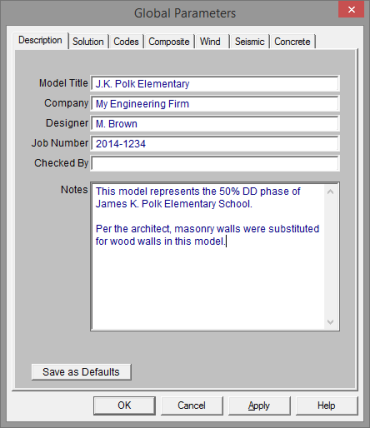
The entries under the Description tab are used to enter descriptive information such as a title for the particular model being defined, the name of the designer and a job number. The title may then be printed at the top of each sheet of the output, and on the graphic printouts of the model. Note that for any of these tabs, you can click on Save as Defaults and then your settings will be saved the next time you open the program.
The Checked By field is intended for the model reviewer to initial upon completion of a model review. Their initials will then be printed on each sheet of the output.
The Notes field is intended for information about the model that may be useful for the engineer or reviewer to refer to.
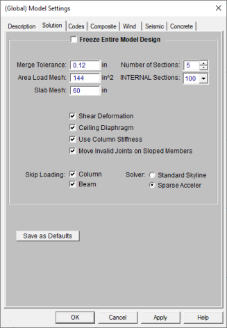
The entries under the Solution tab are used to control settings that affect the general solution of the model.
Number of Sections controls
how many places you receive reported
Number of Internal
Sections controls how many places along each
Note:
When checked, the Freeze Entire Model Design box will disable the program’s redesign capabilities and no beam or columns will be resized during a solution.
Check the Shear Deformation box if shear deformation considerations are to be included in the model solution. See Member Shear Deformations for more information.
The Area Load Mesh is used to determine the maximum size when meshing an area load and attributing the load to members. See Area Loads to learn more about this.
The Slab Mesh is used to define the maximum mesh size of finite elements created for slab floors utilizing RISAFloor ES. No plate generated will have a side dimension larger than what is defined here. There are minimum numbers of plates required between control points, so smaller meshed areas will occur in places with more closely spaced elements.
The Merge Tolerance is used as the maximum
distance 2 points
can be apart and still be merged together. It is also used when
scanning for crossing members and for unattached joints along the spans
of
The Solver to be used during solution may be selected by clicking the radial button next to Standard Skyline or Sparse Accelerated. See Solution for more information on these two options.
Note:
We have removed the Show Factored End Reactions check-box. This box was previously used to define whether you want your beam end reactions to show up as being factored or not (using 1.0 instead). The graphical end reactions will now be shown based on which load combinations are checked in the "Connection" column of the Load Combinations - Design tab. If you want to design your members to factored loads but want the unfactored reactions to show up graphically you would create two sets of load combinations where the factored LC's have the "Hot Rolled Steel" column checked and a set where the "Connection" column is checked.
If the Use Column Stiffness box is not checked, columns will be viewed as simple supports with no rotational stiffness of their own. If this box is checked the column’s rotational stiffness will be calculated based upon the column material, moment of inertia, orientation and story height. For more information see the Distribution of Moments section of the Column Results.
The Move Invalid Joints on Sloped Members is used when you are adding joints to a member after it has already been sloped. If you slope a roof level, then later add members or point loads to the sloping members, these joints are created at the base elevation of the floor. If this box is checked then, at solution time the program will move those joints up to the sloping member. This check-box is checked by default. If you have problems at solution time with your sloping members, you may consider un-checking this box for troubleshooting.
If the Skip Loading box for Column or Beam is checked, the program will automatically design the members for the controlling combination of unbalanced live load at each floor. When the box is unchecked for columns, the columns will only be checked for the case where gravity loads from all sides of the column act concurrently. For more information see Column Skip Loading.
The Ceiling Diaphragm setting is only applicable when the roof of the model is sloped. When the roof is sloped and a rigid or semi-rigid diaphragm is used, this setting must always be turned on because the program does not support sloped rigid or semi-rigid diaphragms. For more information on how this setting affects Flexible diagrams see the Diaphragms topic.

The settings under the Codes tab control which design code is used for code checks for each material type, as well as the codes to be used for live load reduction and floor vibration checks.
The HR Steel entry indicates which code is to be used for the design of hot rolled steel. For more information see Hot Rolled Steel Design.
Note:
The Connection entry indicates which code is to be used for connection design. This entry is only considered if you are also using RISAConnection. See the RISAConnection Integration topic for more information.
The CF Steel entry indicates which steel code is to be used for the design of cold formed steel. For more information see Cold Formed Steel Design.
The Wood entry indicates which wood code is to be used for the design of wood, including wood walls and structural composite lumber. For more information see Wood Design.
Note:
The Concrete entry indicates which
concrete code is to be used in the design of concrete members
Note:
The Masonry entry indicates which masonry code is to be used for the design of masonry walls. For more information see Masonry Design.
Note:
The option for Beam Vibration checks is the AISC Design Guide #11, both the 1st and 2nd Edition. When this calculation is turned on, you may adjust the Damping ratio used your floor system.
The Joist Vibrations check is based on the Steel Joist Institute Technical Digest 5. You can adjust the Damping ratio used in these calculations.
The Live Load Reduction criteria entry indicates which code to use for live load reduction. Floor live load reduction applies to the Live Load and Live Load Special load categories. The Roof option applies to Roof Live Loads.If you do not want live loads to be reduced you may specify " none".
When you have multiple point loads framing into a joist-girder, the Joist Girder Load Tolerance sets the maximum load variation to be allowed when specifying that standard joist girder call-out. When the load variation exceeds this, the call-out will switch to a more complex format for a custom joist girder call-out.
If you do not want a particular code check to be performed you may specify "None" in the drop down list of available codes.
The options on the Composite tab are specifically related to composite steel beam design.
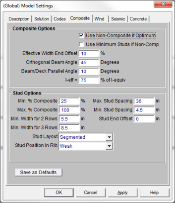
When the Use Non-Composite if Optimum checkbox is unchecked, all beams which are marked as Composite and which have Composite Deck on them are forced to be composite, meeting the Min. Percent Composite specified on this same tab in the Model Settings. This can result in beams or stud layouts that are over-conservative with respect to strength and serviceability requirements. When this box is checked, the program will design the beam as non-composite if the non-composite beam size is more economical than the composite beam size which meets the Min. Percent Composite.
The Use Minimum Studs if Non-Comp box is only available if the Use Non-Composite if Optimum box is checked. When this box is unchecked, non-composite beams will not be detailed with any studs. When this box is checked, a small number of studs are detailed on the beam, equal to the beam length divided by the Max Stud Spacing. These studs serve no purpose for strength or serviceability, and do not affect any capacities or code checks in the program.
The Effective Width End Offset specifies the percent of the beam ends to ignore in determining the effective width. See Effective Widths for more information.
The Orthogonal Beam Angle gives the minimum angle that two beams can make with each other and still be considered perpendicular. Perpendicular beams will not encroach on each other’s effective widths. See Effective Widths for more information.
The Beam / Deck Parallel Angle gives the maximum angle between a beam and the deck for which they can be considered parallel. It is recommended to set this value greater than zero, to allow for minor tolerances within the program.
The I-Effective = %I-Equivalent factor allows the user to make the effective moment of inertia a certain percentage of the equivalent / elastic value based on elastic theory. Commentary to the AISC specification would suggest appropriate values in the range of 70% to 85%. Refer to the Hot Rolled Steel - Composite Beam Design topic for more details.
Min. Percent Composite specifies the minimum percent composite action allowed for composite beams.
Max. Percent Composite specifies the maximum percent composite action allowed for composite beams.
The Min Stud Spacing and Max Stud Spacing control the allowable stud spacing.
The Stud End Offset is used to specify the length of the beam ends that may be unsuitable for stud placement due to construction or connection issues.
The Minimum Width for 2 Rows and Minimum Width for 3 Rows specify the flange widths that can accommodate multiple rows of studs.
The Stud Layout option gives you the ability to choose between uniform stud spacing and segmented spacing.
The Stud Position in Rib option gives you the ability to choose between strong and weak position of studs (Rp, for the AISC code). For the Canadian code this give you the option to choose between studs centered in the rib deck and studs off center in the rib deck. Refer to the Studs section of the Composite Beam Design topic for more details.
The options on the Wind tab present the Model Settings that are specifically related to calculation of code prescribed Wind Loads. This information will be used by RISA-3D to automatically generate the lateral loading on your structure.
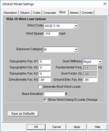
See the Wind Load topic for more information on these inputs.
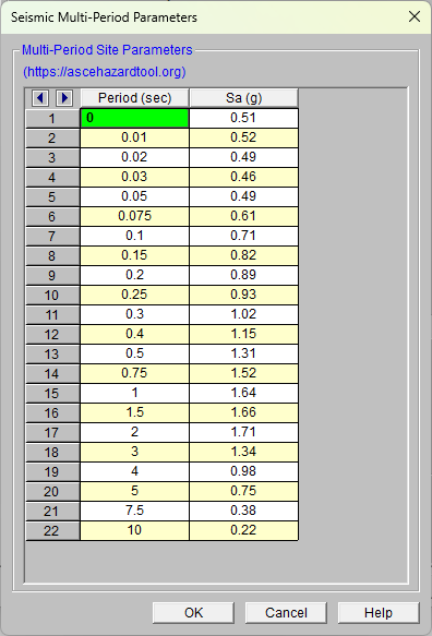
The options on the Seismic tab present the Model Settings that are specifically related to calculation of code prescribed Seismic Loads. This information can be used by RISA-3D to automatically generate the Lateral Loading on your structure. Depending on which Seismic Code you select will depend on the input options that you have.

Most of the input fields on this tab are discussed in the Seismic Load topic. Below are a few inputs which are specific to this tab. See the section Drift Calculations to see how Rho, Cd, Drift Category and Risk Category affect the calculation of story drift results.
(Ω) is the Overstrength Factor. This can be included in the seismic load combinations generated by the LC Generator.
The Redundancy Factor (ρ) is based on the extent of redundancy in your structure. This can be included in the seismic load combinations generated by the LC Generator.
The Diaphragm Mass Self Weight Options allows the user to discount certain portions of the dead weight of the structure for seismic mass calculations. By default all the checkboxes are checked. This may be used if you want to manually add all of the seismic mass to the structure for a specific application.
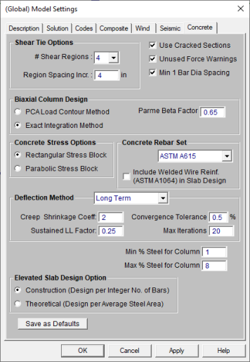
The entries under the Concrete tab contain options related to
the analysis and design of concrete
The Shear Tie Options allow you to control the Number of Shear
Regions that will be used when detailing
a beam
The Concrete Stress Options allow you to choose what type of stress block to consider in your analysis. The options are the constant Rectangular Stress Block and the Parabolic Stress Block. See Parabolic vs. Rectangular Stress Blocks for more information.
Check the Used Cracked Sections box if you want to modify the member and wall stiffnesses by the Icr Factor as described in both the Concrete - Design and Wall Panels topics.
Check the Unused Force Warnings check box to see force warnings on the detail report.
Checking the Minimum 1 Bar Dia Spacing box will allow a minimum spacing of one bar diameter between parallel bars. Otherwise, RISA will default to a two bar diameter or one inch clear spacing, whichever is greater, to allow for lap splices and continue to maintain adequate spacing between parallel bars.
The Concrete Rebar Set allows you to choose from the standard ASTM A615 (imperial), ASTM A615M ("hard" metric, i.e. #8M is an 8mm bar), prENV 10080 (Euro), CSA G30.18 (Canadian), and AS/NZS 4671:2001 (Australian/New Zealand) reinforcement standards.
The Include Welded Wire Reinf. (ASTMA1064) in Slab Design allows you to design a slab using Welded Wire Reinforcement.
Note:
Users shall choose the correct material in the Materials Spreadsheet to account for ASTM A1064 steel.
Welded wire reinforcement is only available for
Only ASTM A1064 deformed bar sizes are available.
Deflection Method options allows you to choose from None, I Cracked/Elastic or Long Term. This only applies to a concrete slab floor.
The Minimum % Steel for Columns allows you to choose the minimum percentage of reinforcement steel to be used in a concrete column section. The percentage entered will be multiplied by the gross area of the column section to determine the minimum amount of reinforcement required in each column. It should be noted that the minimum percentage allowed by ACI 318-14 Section 10.6.1.1 (ACI 318-11 Section 10.9.1) is 1%.
The Maximum % Steel for Columns allows you to choose the maximum percentage of reinforcement steel to be used in a concrete column section. The percentage entered will be multiplied by the gross area of the column section to determine the maximum amount of reinforcement allowed in each column. It should be noted that the maximum percentage allowed by ACI 318-14 Section 10.6.1.1 (ACI 318-11 Section 10.9.1)1 is 8%.
The Elevated Slab Design Option is only visible when you have elevated slabs. This option offers a choice between two methods, namely the Construction method and the Theoretical method, for the design of the slab rebar. The Construction method, which is the default method employed by the program for a significant period, determines the design of the slab based on an integer number of rebar. This method operates under the assumption that if the strip width divided by rebar spacing is not an integer, an additional rebar will be provided to guarantee the presence of a rebar at each end of the design strip. On the other hand, the Theoretical method is a new method added later that enables the program to calculate the rebar area based on the average value, where the rebar area equals As (single rebar) multiplied by the Strip Width divided by Spacing. However, it is crucial to note that this method may not always result in an integer number of rebar so unlike the Construction method, the results for Theoretical method will have no info of rebar amount.
Note:
Concrete cover for beams and columns is specified under Design Rules under the Concrete Rebar tab.